Rpm Tachometer Wiring Diagram
nest Hello Wiring Diagram, Nest Hello Advanced Wiring Diagram, 6.25 MB, 04:33, 63,749, gt8monster, 2018-06-16T10:14:46.000000Z, 19, Nest Hello Doorbell: 18 Questions/Answers You Need To Know - Smart Home Point, www.smarthomepoint.com, 1057 x 852, png, nest diagram hello doorbell wiring google camera chimes chime install multiple lh4 googleusercontent answers questions know need pre, 20, %ef%bb%bfnest-hello-wiring-diagram, Anime Arts
Connect one of the wires in the twisted pair (from magnetic sensor) to the "s" terminal. Connect the other wire in the twisted pair (from the magnetic sensor) to the negative (. ) terminal (also noted in figure 2 as the 'ground stud') connecting to alternator (alternator driven models) Alternator* generator* and inductive* senders *diesel applications c g or s generator sender:
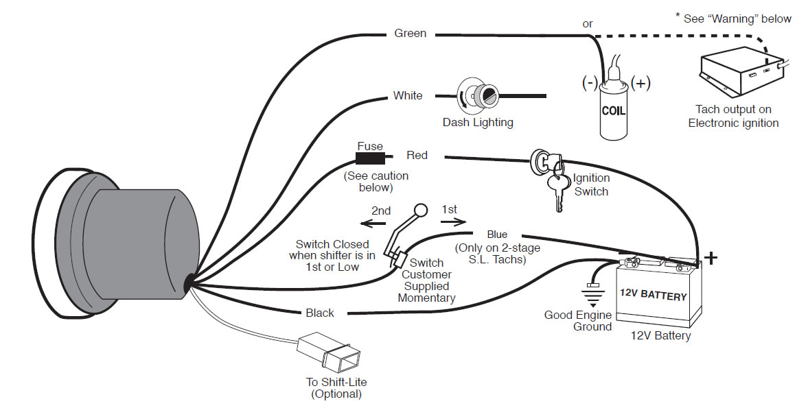
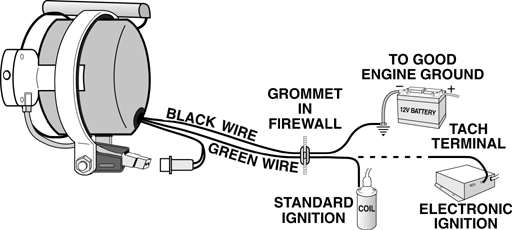
This is the circuit diagram of digital tachometer / digital rpm meter which can be used for cars or motorcycles with 2 and 4 stroke petrol engines with any number of cylinders and contact breaker or electronic ignition systems. May be used as a general purpose revolution counter. Rpm ˘ diagram b vdo programmable tachometer dimensional drawings 3¹⁄₈ (80mm) 3³⁄₈ (85mm) 4 (100mm) 3¹⁄₈ (80mm) 3³⁄₈ (85mm) 4 (100mm) 3. 32 (84mm) 3. 56 (89mm) 4. 16 (104mm) tachometer: "a" "b" sensor installation the sensor necessary to provide the signal to your new vdo tachometer is not included. The tachometer is configured at the factory for 4 ppr. To change the ppr on tachs with three buttons, follow the steps below: With no power applied to the tach, press and hold the set button. Apply power to the tach by turning the ignition key to the "accessory" or "on" position. Do not start the engine!
rwdesignbuild: Aftermarket Tachometer Wiring Diagram
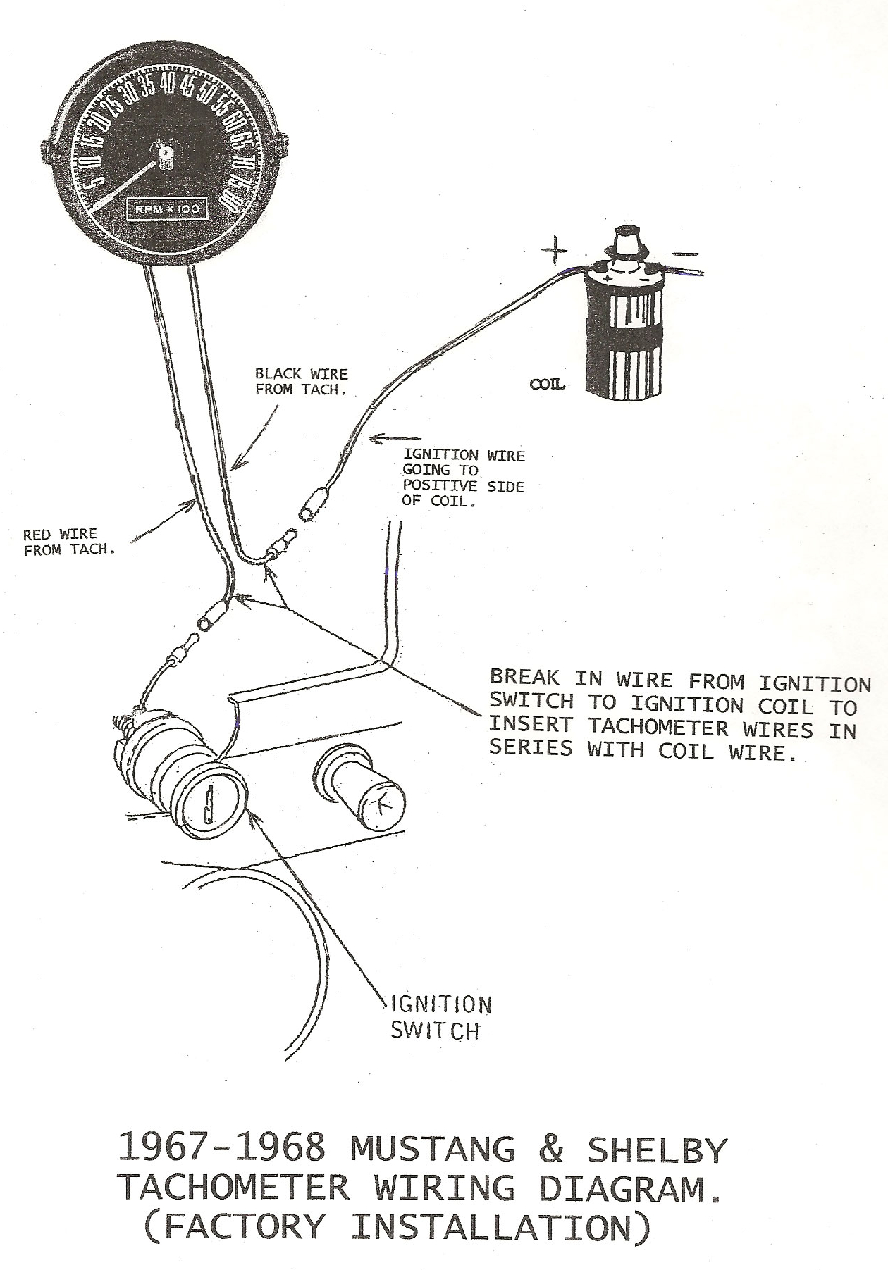
[DIAGRAM] Mustang Rpm Gauge Wiring Diagram 06 FULL Version HD Quality Diagram 06 - DIAGRAMLOVIEM
![Rpm Tachometer Wiring Diagram [DIAGRAM] Mustang Rpm Gauge Wiring Diagram 06 FULL Version HD Quality Diagram 06 - DIAGRAMLOVIEM](https://static-cdn.imageservice.cloud/1098603/tach-gauge-wiring-diagram-wiring-diagram-online.jpg)
Aftermarket Rpm Gauge Wiring Diagram - Wiring Diagram Networks

I'm trying to install a tachometer rpm gauge in my 2000 Nissan Sentra xe and wanted to know

~: Wiring Diagram For Aftermarket Tachometer

Defi Rpm Gauge Wiring Diagram

Jdm Tachometer Wiring Diagram

Aftermarket Rpm Gauge Wiring Diagram - Wiring Diagram Networks

Suzuki Tachometer Wiring Collection - Wiring Diagram Sample
